In the solid modeling approach, Fidelity Pointwise creates models and quilts while importing the initial CAD data. Models are topological CAD entities that allow for watertight meshing over gaps and cracks existent in the underlying geometry. Quilts are meshing regions defined at the CAD level. Furthermore, while a model is a watertight representation of the geometry, quilts are the regions within the model that hide unnecessary complex topology in the underlying geometry by defining meshing region boundaries. Initially, each CAD surface is associated with a single quilt; as long as the quilts belong to the same model, they can be assembled into larger meshing regions (i.e. quilts) using the command described in this section.
The Assemble Quilts command becomes enabled, independently of the current selection, only when models are present. However, once the panel is open, only database quilts will be available for further selection.
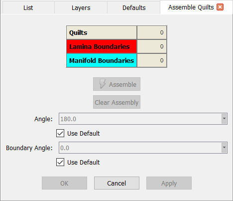
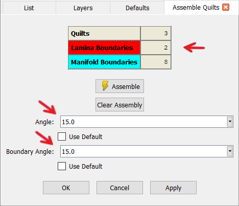
Entering the Assemble Quilts command with no database quilts selected will present the panel shown in the figure above. As quilts are selected, the total is shown in the table as Quilts. The table also presents the number of Lamina Boundaries (color coded in red) and Manifold Boundaries (color coded in light blue). The former corresponds to surface edges used by exactly one surface. The latter, corresponds to surface edges used by exactly two surfaces.
The Assemble command will become available once at least one database quilt is selected. This command will combine the selected quilts into as few larger quilts as possible subject to the turning Angle. Quilts meeting at a common edge with turning angle smaller than the value specified in the Angle field, will be combined into a larger quilt. Uncheck Use Default to adjust the turning angle as needed.
A turning angle can be specified in the Boundary Angle field so that quilt bounding curves can be joined during the quilt assemble operation. Such curves will be joined where the turning angle at their common end points is smaller than the value entered in this field.
After the assemble operation is complete, the total number of assembled quilts is then shown in the table as Quilts. Use the Clear Assembly command to clear out the current assembled quilt while leaving the selection active.
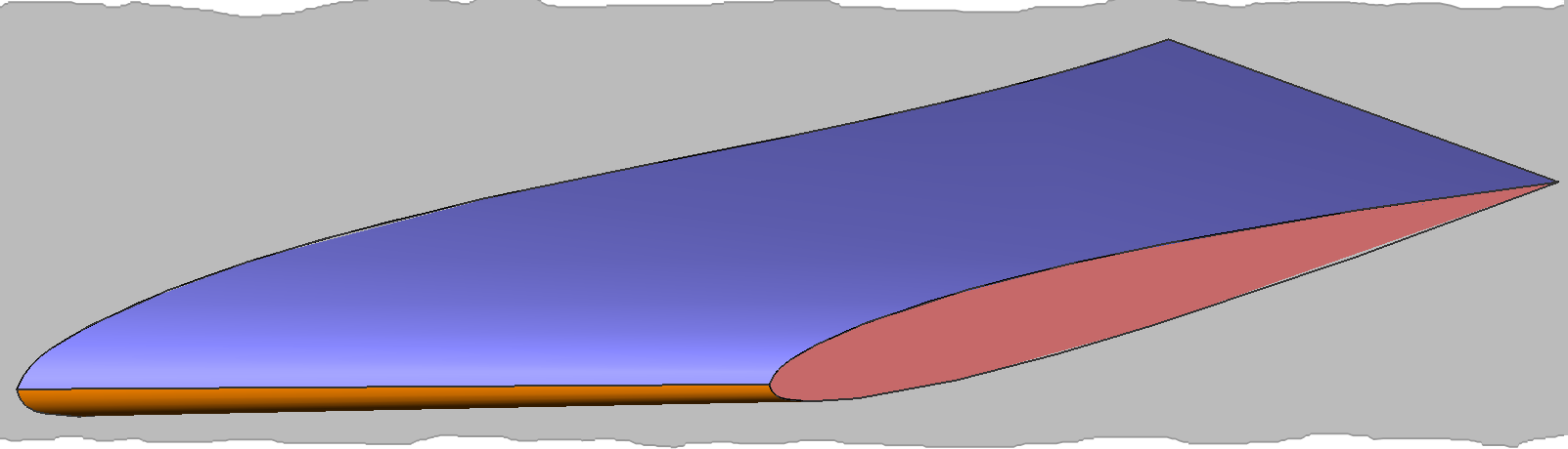
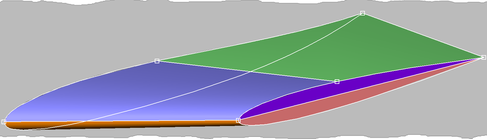
The simple database shown below will be used to illustrate the database quilts assembly process.
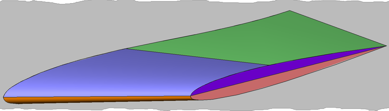
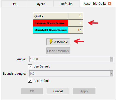
Selecting all the quilts rendered in rainbow colors (two for the upper fin surface, one for the lower fin surface, and two for the fin’s tip) updates the table in the Assemble Quilts panel and enables the Assemble command as shown in the figure below. Also note that when quilts are selected, the ends of their bounding curves are displayed as small white squares for clarity.
In this example, leaving the Angle parameter with its default value of 180 degrees, would assemble all the database quilts together at common manifold boundaries. As seen in the image below, setting this parameter to 15.0 degrees, produces a more appropriate set of three meshing regions (i.e. quilts) that reflects the original engineering intent of the geometry. Furthermore, the Boundary Angle parameter is also set to 15.0 degrees to join all the quilt bounding curves according to their turning angle.
The light blue edges shown in the image below indicate manifold connections between quilts; each common edge is used exactly twice between two adjacent quilts. The table shown below indicates that there are 8 Manifold Boundaries and 2 Lamina Boundaries. The latter are surface edges used by only one surface.
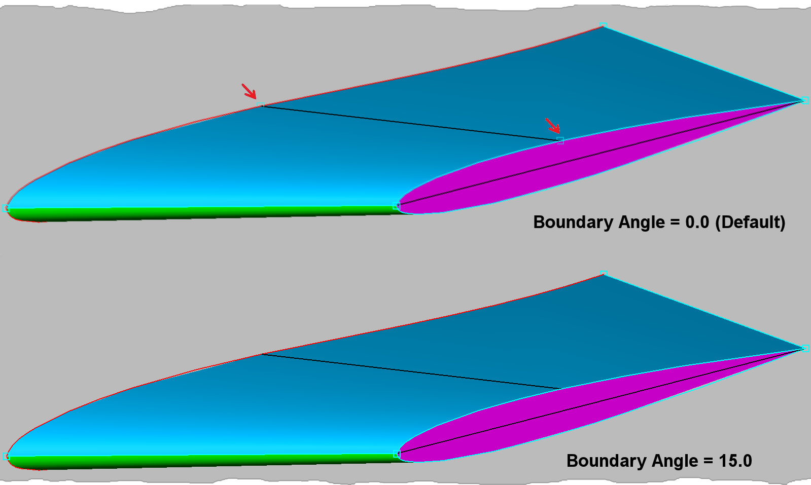
Each resulting quilt is rendered shaded in a different color for clarity. In this case, there are three quilts: one for the upper fin surface, one for the lower fin surface, and one for the fin’s tip. Two Lamina Boundaries remain for the root of the fin. These assembled quilts now logically represent mesh topological regions.