Candidate database entities to be projected to are those that are visible unless target database entities are selected explicitly within the Project
command via the Target Database Selection tools. The candidate database entities for projection can be
modified by changing the Show/Hide status of the entity (see the Attributes section for more details)
or by turning layers on or off (see the Layers section for more details). Surface and quilt
entities in layers that are on and are set to Show will be projected onto. Turning off the layer containing the entities that the grid points should
not be projected onto, or changing the entity’s display status to Hidden, has two effects. First, it prevents the projection algorithm from placing
the grid points on the wrong surface. Second, it reduces the number of surfaces the projection algorithm has to evaluate and, therefore, the process will run
faster. It is possible to project connectors onto database curves. However, only connectors can be selected for the Project command, and the desired
target database curves must be explicitly selected via the Target Database Selection tools.
Tip: For complex geometries, select your target database surfaces within the Project panel before using a Closest
Point projection. Alternatively, you can also isolate the layer containing the database surfaces onto which you plan to closest point project. Either
one of these methods will help ensure that all the points in the selected grid entity are projected onto the appropriate surfaces.
Select Edit, Project. Select the Type of projection, the Direction of the projection (if applicable), and whether the Interior
Only or end points as well should be projected in the Projection Control frame. If a specific database or set of database entities are the
target, select them in the Target Database Selection frame. Click Project. If the projection is not satisfactory, change the projection
settings, then click Project again. The projected entity will be re-projected based on the new settings. Clicking OK will save the projected
entity, while clicking Cancel will exit the Project panel without saving any changes.
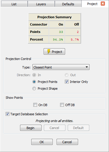
The Project panel provides multiple options for projecting an entity in addition to a summary of projection statistics.
Within the Project panel, the Projection Summary table provides details about the points and percentage of points that have been projected
on the connector and/or domain levels or provides a percentage only for database curve projections.
- Points On: Refers to the number of points in selected grid entities that are on a database entity.
- Points Off: Refers to the number of points in selected grid entities that are off of a database entity.
- Percent On: Refers to the percentage of points in selected grid entities that are on a database entity. For database curves this represents
the total portion of the curve on the target database.
- Percent Off: refers to the percentage of points in selected grid entities that are off of a database entity. For database curves this
represents the total portion of the curve off the target database.
Beneath the Projection Summary table, you will find the Project command which will apply any settings you have made in Projection
Control to either the entire visible database or those entities selected via the Target Database Selection command. Additionally, in
the Show Points frame you can toggle on color-coded rendering of all grid points based on their projection status: green for On DB and red
for Off DB.