Description
There are several different areas within the Flashpoint toolset that require entities be classified in order to determine what kind of treatment is applied. Although the default classifications work well in most situations, filters are provided as a way for users to have more control over this classification.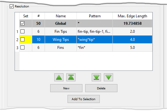
Use the New command to create a new filter and the Delete command to
delete the currently selected filter. Use the Add To Selection button to add the
entities in the selected filter to the current selection in the Display window. The up
and down green arrow buttons
(![]() ,
,
![]() ,
,
![]() , and
, and
![]() )
can be used to increase or decrease, respectively, the selected filter's
priority, which is displayed as a read-only integer in the first column of the table.
)
can be used to increase or decrease, respectively, the selected filter's
priority, which is displayed as a read-only integer in the first column of the table.
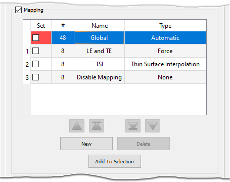
Entities can be manually added to a filter using the checkbox in the Set column or automatically selected by specifying a wildcard pattern. The # column contains a read-only integer showing the number of entities currently selected by a filter and is updated as entities are added to or removed from a filter's selection. Edit the Name column to set the name for the filter.
For more information about resolution, mapping, stretching, and boundary condition filters, please review the relevant sections of this User Manual. For more information about using filter pattern tables and wildcard pattern matching, see the sections below.
Filter Priority
In regions where multiple filters conflict, the filter with the highest priority (i.e. lowest integer value) takes precedence. All user-defined filters automatically rank higher than the default filters, which do not display a priority. Although entities may be associated with the pattern of multiple filters, they can only be selected by one filter at a time. If an entity's name matches the pattern of multiple filters, the entity is selected by the filter with the highest priority.
Note: Higher priority filters that match an entity's name using a
wildcard pattern may have !pattern items added to them so that lower priority
filters with explicit entity names select the appropriate entities.
Filter Pattern Tables
Filter pattern tables are provided as an easy way to quickly build up complex patterns for filter selection. Use the New command to create a new filter pattern and the Delete command to delete the currently selected filter pattern.
Note: Resolution filters are the only filter type within the Flashpoint toolset that does not currently make use of filter pattern tables. Instead, you can specify multiple patterns in the Pattern field using a comma separated list. To edit the pattern for resolution filters, simply double click in the Pattern column of the Resolution table.
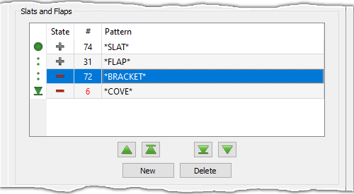
The filter patterns are applied in the order in which they appear in the table: the first
pattern applied is denoted with the begin icon
(![]() )
and the last pattern with the end icon
(
)
and the last pattern with the end icon
(![]() ).
The up and down green arrow buttons
(
).
The up and down green arrow buttons
(![]() ,
,
![]() ,
,
![]() , and
, and
![]() ) can be used to move the selected pattern's position up or down in the table.
) can be used to move the selected pattern's position up or down in the table.
Tip: Since filter patterns are applied in the order in which they appear in the filter table, changing the order of the patterns can change which entities are selected by the filter. It is usually a good idea to place all additive patterns at the beginning of the list and all subtractive patterns at the end.
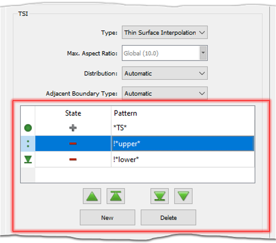
The State column displays an icon denoting whether the filter pattern is additive
(![]() )
or subtractive (
)
or subtractive (![]() ). Additive patterns add
entities that match to the filter's selection and subtractive patterns remove entities that match from the
filter's selection. Simply double click the icon in the filter pattern table to toggle between states.
). Additive patterns add
entities that match to the filter's selection and subtractive patterns remove entities that match from the
filter's selection. Simply double click the icon in the filter pattern table to toggle between states.
Double click in the Pattern column to enter a pattern for the filter. Only a single
pattern can be specified in each field (i.e. a comma separated list of patterns cannot be
specified). If the State is subtractive, the ! wildcard will automatically
be added to the pattern to specify exclusion. Likewise, adding the ! wildcard to an
additive pattern automatically changes the State to subtractive.
The boundary condition filter table in the Automatic Volume Mesh command also contains an additional # column which displays a read-only integer indicating the number of domains currently selected by each pattern in the filter. This column is updated as the filter definition is updated.
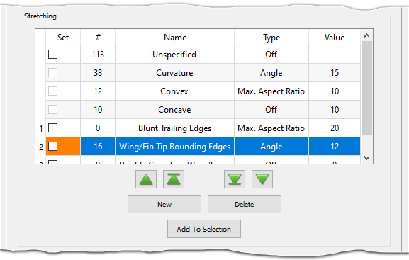
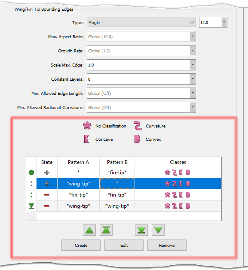
Note: To make changes to patterns in the stretching filter pattern table, you must use either the Create or Edit buttons to enter a special editing mode. For more information about specifying stretching filters, please see the stretching filter section of this User Manual.
Since stretching filters are more complex (they require a set of two patterns and allow you to further restrict selection based on edge classification), the stretching filter pattern table is read-only. Instead, this table uses the Create and Edit commands to enter a special editing mode that contains options for updating the pattern's definition. Please refer to the stretching filter section of this User-Manual for more information about how to define stretching filters, including a table with detailed examples.

Wildcard Pattern Matching
Entities are selected by a filter if their name matches the pattern in the
Pattern column of the filter pattern table. If a filter's pattern list is empty, the filter
is disabled. Wildcard matching supports single (?) and multiple (*)
character matching as well as exclusion (!). If the pattern needs to include a
special character (such as a comma, space, or wildcard), it must be escaped using the \
character. The table below shows a list of wildcards with examples.
| Wildcard | Example | Meaning |
|---|---|---|
* |
wing* |
Matches any name that starts with wing |
*wing* |
Matches any name that contains wing | |
? |
win? |
Matches any 4-character name that starts with win |
! |
!AB* |
Excludes any name that starts with AB |
\ |
A\,* |
Matches any name that starts with A, |
!\\ AB* |
Excludes any name that starts with \ AB |
Tip: It is a good idea to organize and rename quilts before entering the Automatic Surface Mesh panel as this will make it easier to define filter patterns. A group of quilts can be renamed simultaneously using the Base Name field in the Attributes command.
Alternatively, the filter pattern can also be updated manually by selecting an entity or group of
entities in the Display window and clicking on the checkbox in the Set column of
the appropriate filter. This updates the pattern for the filter with an explicit list of the
entity names. Similarly, unchecking the checkbox in the Set column removes entities
from a filter pattern. If the entity names were explicitly defined, they are simply removed from
the pattern. Otherwise, if the entity names match a wildcard pattern, the pattern is updated
with a list of explicit entity names to be ignored by the filter using the ! wildcard.
Caution: Be careful when using explicit entity names in the pattern of a filter as deleting the entity or changing its name does not update the filter's pattern.