Description
The Boundary Conditions panel provides tools for creating, assigning, and deleting boundary condition filters to control how boundaries are used by T-Rex for growing layers of anisotropic cells to form the boundary layer.
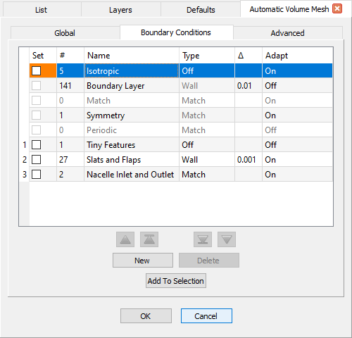
The first five rows of the Boundary Conditions table show the default boundary condition filters to which domains are automatically assigned by Automatic Volume Mesh: Isotropic, Boundary Layer, Match, Symmetry, and Periodic. These filters cannot be deleted or renamed nor can their Type be edited. Default filters are automatically placed at a lower priority than user-defined filters. See the Default Boundary Condition Filter section below for more information on which domains are automatically assigned to each default filter.
The buttons (New, Delete, Add to Selection,
![]() ,
,
![]() ,
,
![]() , and
, and
![]() ) and
first 4 columns in the table (priority, Set, #, and Name)
all function the same as other filters in the Flashpoint toolset. Please refer to the
Flashpoint Filters
section for more information.
) and
first 4 columns in the table (priority, Set, #, and Name)
all function the same as other filters in the Flashpoint toolset. Please refer to the
Flashpoint Filters
section for more information.
The Type and Δ columns are specific to boundary layer growth and are disabled if the Boundary Layer parameter on the Global tab is set to Off. Otherwise, use the dropdown in the Type column to choose from the boundary condition types described below. For more information about T-Rex and its boundary condition types, please refer to the T-Rex BC section of this User Manual.
Caution: Even though the Angle, Aspect Ratio, and Max. Aspect Ratio boundary condition types appear in the list, these types are specific to surface meshing and should not be used for volume meshing. For more information on how to use these boundary conditions in your surface meshing, please review the Automatic Surface Mesh and 2D T-Rex sections of this User Manual.
- Wall: Specifies that the assigned bounding domains have layers of anisotropic cells grown off of them. The value in the accompanying Δ column defines the initial height of the anisotropic cells and is tied to the Wall Normal Spacing parameter on the Global tab. Editing the value in either location updates the corresponding field on the other tab.
- Match: Specifies that the interior grid point distributions on the assigned
bounding domains should be updated to match the growth of the anisotropic layers.
Tip: The Match boundary condition type is best suited for domains that are adjacent to domains set to a Wall or Adjacent Grid boundary condition since it will automatically update the domain's interior cell distribution to match the growth profile of the anisotropic layers being grown.
- Adjacent Grid: Specifies that the assigned bounding domains have layers of
anisotropic cells grown off of them while matching the initial cell height of an adjacent
block.
Note: The Adjacent Grid boundary condition should only be used for domains that interface with another block and both sides of the interface need to be used for growing the boundary layer. In that case, you can set the interface in one of the blocks to an Adjacent Grid boundary condition to use the same initial spacing in both blocks.
- Off: Specifies that the assigned bounding domains do not have anisotropic cells grown off of them.
The Adapt column allows you to specify whether or not the domains assigned to that boundary condition should be adapted to sources and other size field influencers. Use the dropdown to toggle between On and Off. By default, Adapt is set to Off for newly created boundary condition filters.
Default Boundary Condition Filters
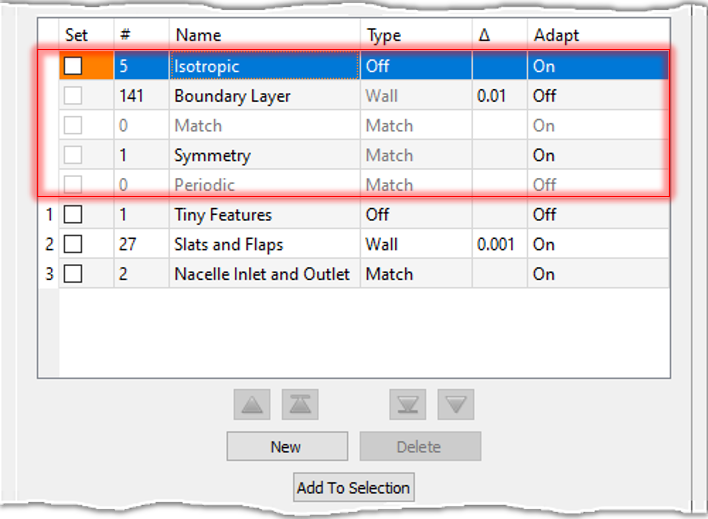
The first five rows of the Boundary Conditions table display the default boundary condition filters to which Automatic Volume Mesh automatically assigns all of the bounding domains:
- Isotropic: Domains created by Automatic Volume Mesh that are not within tolerance of a symmetry plane and pre-existing domains that do not fall into one of the other classifications are automatically classified as Isotropic. The Type for the Isotropic boundary condition is Off and by default Adapt is turned On.
- Boundary Layer: Domains are automatically classified as Boundary Layer if they are geometry-constrained. The Type for the Boundary Layer boundary condition is Wall and by default Adapt is turned On.
- Match: Domains are automatically classified as Match if they are free from geometric constraints, not linked to a structured domain, and adjacent to one or more domains assigned to a Wall type boundary condition. The Type for the Match boundary condition is Match and by default Adapt is turned On.
- Symmetry: Domains that are created by Automatic Volume Mesh and are within tolerance of a symmetry plane are automatically classified as Symmetry. The Type for the Symmetry boundary condition is Match and by default Adapt is turned On.
- Periodic: Domains are automatically classified as Periodic if
they are flagged as being part of a periodic pair. The Type for the
Periodic boundary condition is Match and Adapt is
turned Off and disabled. Please review the description of the
Periodic command for more information about
creating and using periodic domains.
Note: Domains that belong to a periodic pair always have their periodicity maintained (i.e. they remain identical) regardless of boundary condition Type or Adapt status. If you wish to change the Type simply assign both domains to a user-defined boundary condition with the desired type. If you wish to enable adaption for the periodic pair, it is recommended to assign one domain to a boundary condition with Adapt turned On and assign the other to a boundary condition with Adapt turned Off. This will still update both domains, but is more robust since the size field may produce slightly different results for each domain.
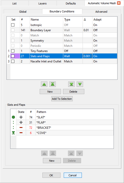
User-Defined Boundary Condition Filters
Selecting a user-defined boundary condition filter in the Boundary Conditions table brings up a secondary frame with the same name as the selected filter that contains controls for editing the filter's definition.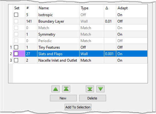
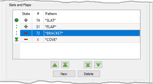
Boundary condition filters are defined by prescribing one or more filter patterns. These are displayed in the table in the filter's frame. This filter pattern table functions similarly to other filter pattern tables within the Flashpoint toolset. Please refer to the Filter Pattern Tables and Wildcard Pattern Matching sections on the Flashpoint Filters page for more information on defining filter patterns.
Tip: Domains created by Automatic Surface Mesh are automatically named according to the name of their underlying quilts. This means that you can use similar name patterns to automatically assign domains to boundary condition filters in Automatic Volume Mesh as you used to assign entities to resolution, mapping, and stretching filters in Automatic Surface Mesh.