The Build Refinement, Voxel command is designed to quickly create voxel refinement blocks used as background blocks in overset grid topologies. Please refer to the Grid, Overset command, for more information regarding overset tools.
The selected entities will be queried for grid spacings which in turn can be used to determine a homogeneous spacing for the new voxel block. Refer to the Spacing Controls section below for more information on setting spacings. Note that the selected entities are not used to form the faces of the new block; only their spacings are used for reference.
Voxel blocks are composed of hierarchical Cartesian cells which are clustered about and sized by the selected entities. Root voxel cell sizes are specified for the rectangular block and recursively subdivided based on the size field determined from the selected grid entities and any sources located inside a region computed as twice the size of the block's extent box. Subdivision stops when the voxel cell sizes match the local size field. Transitions between levels in the Cartesian mesh are made using tetrahedral cells and pyramids in order to maintain point-to-point cell face matching. Users can override the default minimum and maximum cell edge sizes and set a minimum number of cell transition layers using the tools in this panel.
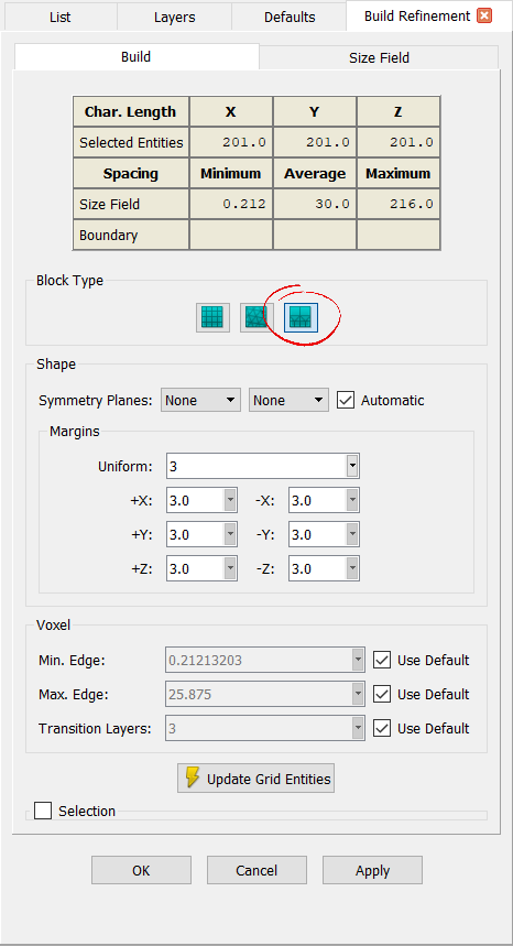
At the top of the Build Refinement panel, you will find a table displaying the X, Y, and Z Characteristic Length of the selected entities. Additionally, the Minimum, Average, and Maximum spacings of the size field and the actual boundaries of the new block are shown. Keep in mind that the size field is computed considering the initial selected entities, any enabled sources, and any additional grid entities marked as size field influencers in the Size Field tab.
The Block Type frame (shown above with the Voxel option circled in red) allows you to choose the block type to be created: Structured, Unstructured, or Voxel. When you enter the Build Refinement panel for the first time, the Block Type will be selected directly via the menu.
In the Shape frame (shown below), you can set up a symmetry plane definition for the new block as well as its extents. By default for Symmetry Planes, the Automatic toggle is checked on. This means that the command will try to determine a single or two planes of symmetry automatically from the selected grid entities. If a symmetry plane is not detected automatically, you can use the first and second pull-down lists to select it manually. Note that using one of the two pull-down lists will uncheck the Automatic toggle automatically. You can recheck this toggle to have the panel restore the automatically detected symmetry plane(s).
In the Margins frame, you will find fields to set the extents of the new block in the X, Y, and Z coordinates. The Uniform text field allows you to enter a single number which will be used in all three coordinate directions. This value will automatically populate the individual coordinate direction fields just below (i.e. +X, -X, +Y, -Y, +Z, and -Z). The individual fields can also be used to enter unique numerical values for each coordinate minimum and maximum.

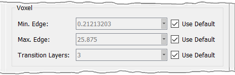
The default Min. Edge and Max. Edge for voxel cells can be changed directly by unchecking Use Default and entering a new value in the corresponding text fields. These values are absolute limiters. Therefore if there is an influence domain selected for the construction of this block type, and that domain has cell edges smaller than the Min. Edge specified, the Min. Edge value is used.
The Transition Layers parameter is a target for the number of layers of equally-sized (i.e. isotropic) hexahedral cells placed between two consecutive transition layers in a voxel block. Note that the transition layers contain a combination of pyramid and tetrahedral volume cells. The default value for this parameter, when Use Default is checked on, is 3.
Finally, you can click Update Grid Entities at the bottom of the panel to preview the bounding domains of the pending new block. If size field refinement or boundary adaption will be necessary, the Solve command for voxel blocks will need to be used. If desired, tools in the collapsed Selection frame will provide a selection mode to reselect the domains to be used by the new block. This would be equivalent to clicking Cancel to exit the command, changing your selection, and entering Build Blocks again.
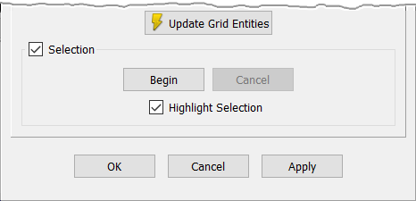
When the new block is complete, click OK to save it and close the panel, click Cancel to discard it and close the panel, or click Apply to save it and continue on to creating another block.