Description
Select more than one connector from the Display window or the List panel and then Create, Extrude, and select the desired extrusion type: Normal, Translate, Rotate, or Path.
A table showing the number of Free connectors, the Number of edges, and the Assembly Method is displayed at the top of the Assemble panel in the figure below. The Free connectors are connectors not currently used in a defined edge. The Number of edges is the number of user-defined edges present. Assembly Method simply refers to whether the edges are being automatically assembled by Fidelity Pointwise, manually defined by the you, or set to one domain per connector.
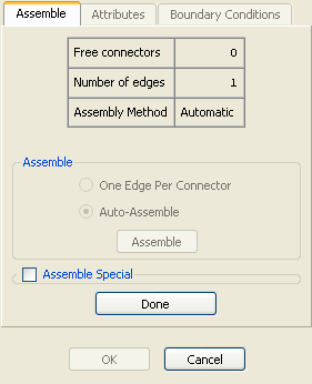
One of two methods in the Assemble frame are used to automatically assemble multiple connectors into edges. Auto-Assemble will automatically assemble the selected connectors into as few edges as possible. One Edge Per Connector will assign one edge per selected connector. The Assemble frame will remember the automatic method used previously (either Auto-Assemble or One Edge Per Connector) for the last extrusion and use that method the next time you enter extrusion.
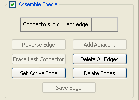
If neither of the automated assembly options create the edges needed for the extrusion, the options in the Assemble Special frame (see figure above) can be used to manual construct the edges needed.
To build an edge, you must first select the set of connectors that will form the edge. When selecting connectors to build an edge, you can use the Add Adjacent command to help speed up the process of selecting adjacent connectors. The Erase Last Connector command can be used to delete the last connector from edge you are currently building. The Reverse Edge will flip the direction of the current edge so that you can remove/add a connector to the opposite end of the current edge.
For situations in which all connectors are currently being used in an edge or edges, you may need to modify an existing edge. To do so, press Set Active Edge and select the edge to modify. Use any of the commands in the Assemble Special frame to change the edge, then press Set Active Edge again to complete the modifications. Additionally, the Delete All Edges or Delete Edges commands can be used to remove the definition of all or some edges from memory. Of these two options, the Delete All Edges command typically provides the fastest way to start building edges from scratch.
Save Edge is used to save each edge after assembly.
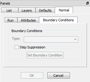
The Boundary Conditions tab looks very similar to that of the domain extruder except an additional option of Step Suppression. This option scales the marching step size on the boundaries relative to that on the grid’s interior. The value you enter will be in the range of [-1, 1]. Positive values will increase the boundary step size relative to the interior step size. Negative values will have the opposite effect. The default value is 0.
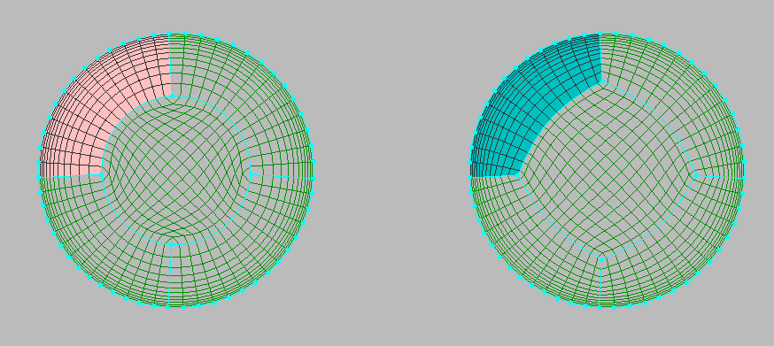
In the figure above, four outer grids in each case were extruded normally into the interior of the circle. The interior grid represents an H grid that was created by assembling edges on the extrusion front. Step suppression was turned off for the left grid but set to -0.4 for the right grid. As a result, the four connectors on the right heading from the circles to the interior grow slower than the interior points. This results in a more square shape middle region where a better quality H grid can be created.