Description
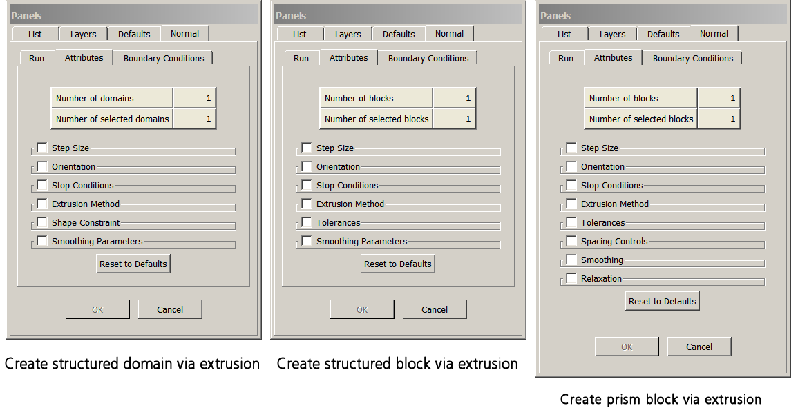
In the Attributes tab you have available a number of attributes to help control your extrusion. Each category of attributes is collapsed by default. Checking a category will expand it an allow you to make changes to those attributes before running your extrusion.
Step Size
In the Step Size frame you can set up your extrusion to march out based on an initial step size (Initial Δs) and geometric progression or by specifying a subconnector(s) for the extrusion to march along. The Method pull-down allows you to choose Geometric Progression or Subconnector for these two methods respectively.
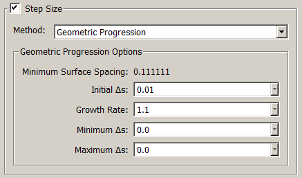
When Geometric Progression is selected, the Geometric Progression Options frame becomes available. In this frame, you can specify the height of the first extrusion step in the Initial Δs text field. The rate at which the cell height will grow with each successive extrusion step is specified in the Growth Rate text field. The minimum and maximum extrusion step height is specified by the Minimum Δs and Maximum Δs text fields. The Minimum Surface Spacing found in the initial extrusion front is shown at the top of this frame for reference. A good rule of thumb for Initial Δs is that it be no greater that ten percent (10%) of the minimum spacing found in the initial front.
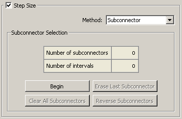
When Subconnector is selected for the step size method, the Subconnector Selection frame becomes available. This frame allows you to select the subconnectors you wish the extrusion to follow by selecting the Begin command and to end selection of those subconnectors with the End command. Erase Last Subconnector deselects the last subconnector selected whereas Clear All Subconnectors deselects all subconnectors. Reversal of the direction of the selected subconnectors is done via the Reverse Subconnectors command.
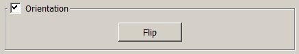
Orientation
In the Orientation frame, you can control the marching direction of the extrusion. When extruding domains into blocks, the Flip command reverses the default extrusion direction which is normal to the selected domains. When extruding connectors into domains, three Orientation commands are available. Set Plane stores a plane which is parallel to the current view plane and in which the edge will be marched. Set Vector uses the current view direction as the edge marching direction. Flip reverses the marching direction of the edge.
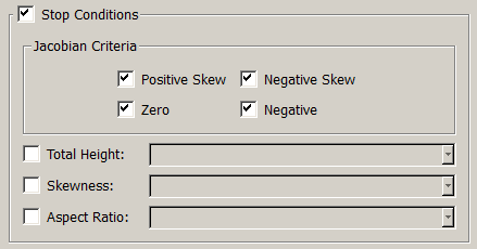
Stop Conditions
In the Stop Conditions frame, you can set grid quality parameters that, when exceeded, stop the extrusion so that you can take corrective action. The Jacobian Criteria, which are on by default for all extrusions, stop the extrusion if a Positive Skew, Negative Skew, Zero, or Negative Jacobian cell is created. The Total Height condition causes the extrusion to stop if the total distance marched by any grid line exceeds the value specified. The Skewness condition stops the extrusion if the minimum skew angle of any cell created exceeds the value specified. The Aspect Ratio condition stops the extrusion if the aspect ratio of any cell created exceeds the value specified.
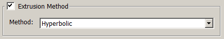
Extrusion Method
In the Extrusion Method frame, you can select the extrusion method to be used via the Method pull-down. Note that only the Algebraic algorithm will be available for extruding structured and/or unstructured domains into prism blocks. On the other hand, if the current grid type is set to Structured (refer to the Set Type section for further details), you can use either the Hyperbolic or the Algebraic algorithms for extruding structured domains into structured blocks.
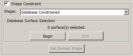
Shape Constraint
The Shape Constraint frame will only be available when extruding connectors into domains. Choose whether you wish the shape of the newly extruded domain to be Free or Database Constrained. Free allows the extrusion to proceed without shape restriction in 3D space. Database Constrained forces each new step of the extrusion to lie on an underlying database surface or surfaces. For the latter choice, use the Begin and End commands in the Database Surface Selection frame to enter into a selection mode allowing you to pick the database surfaces to which the newly extruded domain will be constrained. Informational text is provided just above the Begin and End commands to indicate exactly how many database surfaces have been selected. Any time the Shape has be switched between Free and Database Constrained, you must use the Set Domain Shape command to save the new attribute.
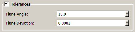
Tolerances
The Plane Angle tolerance serves two purposes. The first one is to determine if an edge assigned to an Arbitrary Plane boundary condition can be considered to be in a constant Cartesian plane. A larger tolerance allows more slop. The second purpose is to determine if a given edge can be assigned to a Constant X, Constant Y, or Constant Z boundary condition (refer to the Boundary Conditions section for further information). If the difference between the normals to the grid cells using the edge and the normal to the appropriate constant X, Y or Z plane is smaller than this tolerance, the boundary condition will not be allowed and an error message will be displayd in the Messages window. The default value for this parameter is 10 degrees.
The Plane Deviation tolerance is used to specify the tolerance within which all connector points must fall for a Constant X, Constant Y, or Constant Z boundary condition to be applied. The default value for this parameter is 0.001.
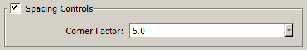
Spacing Controls
The Spacing Controls frame is only available when using the Algebraic method to extrude unstructured domains into blocks. The Corner Factor allows you to locally increase marching step height in concave areas and decrease it in convex areas in an attempt to more rapidly smooth the marching front. The default value is 5.0 and this setting has a valid range of 1.0 to 10.0.
Tip: Smoothing and Relaxation defaults have been optimized for the average extrusion cases encountered. These generally only need adjustment for more complex geometric shapes.
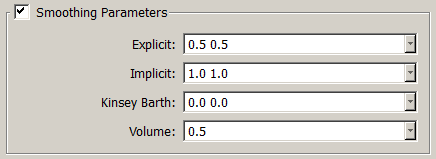
Smoothing Parameters
The Smoothing Parameters frame is only available when using the Hyperbolic method to extrude structured domains into blocks. These parameters are used to prevent grid line crossing and numerical instabilities. Enter the hyperbolic explicit smoothing coefficient for the transverse direction in the Explicit text field. The default value is 0.5. Enter the hyperbolic implicit smoothing coefficient for the transverse direction in the Implicit text field. The default value is 1.0 and the implicit coefficient must be double the explicit coefficient. The Kinsey Barth smoothing is off by default. This smoothing helps to prevent crossing of grid lines in the marching direction and should be set to a value of 3.0 or greater when the front includes severe concavities. The Volume smoothing ranges from 0.0 to 1.0 and has a default value of 0.5. This smoothing determines how rapidly grid clustering in the front will relax. A value of 0.0 will allow clustering to remain intact throughout the extrusion to the final boundary step.
Smoothing
The options available in the Smoothing frame only appear when extruding unstructured domains into blocks. The Quality Metric checkbox is on by default and drives the marching front cells toward ideal cell topology for the cell type. Quads will be driven toward orthogonality and tri’s will be driven to be equilateral. The Interior Only toggle can be used to toggle off Quality Metric smoothing of the boundaries. Maximum Iterations specifies the maximum number of iterations to run the Quality Metric smoothing. Blend Exponent provides a weighting on how the Quality Metric is applied in determining a marching vector for each point in the front. It varies from 0 to 2. At 0 the worst cell, or minimum value of the factor is used to drive the vector. At 2 an average of vectors surrounding is used. In the middle, 1 will provide a blend of these two extremes and is the default setting. Blending is done in an exponential fashion from the 0 value. For most cases Blend Exponent will not need to be adjusted.
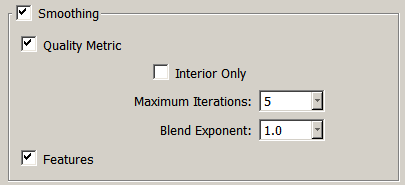
The Features checkbox is on by default and smooths the marching direction vectors for all connectors by taking into account normals to the adjacent cells weighted by cell area. Turning off this toggle will remove this influence of adjacent cell normals and will facilitate starting a difficult extrusion which includes very sharp edges in the initial front. For example, the edge of a control surface of an aerospace vehicle.
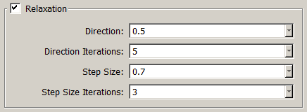
Relaxation
The settings in the Relaxation frame are only available for the Algebraic method. Direction smooths the marching normals locally via a Laplace style filter. This coefficient has a valid range of 0.0 (no influence) to 1.0 (maximum influence). The default value is 0.5. Direction Iterations determines the number of passes the Laplace filter will make per extrusion step. The default is 5. Step Size smooths the marching step size locally via a Laplace style filter. This coefficient has a valid range of 0.0 (no influence) to 1.0 (maximum influence). The default value is 0.7. Step Size Iterations determines the number of passes the Laplace filter will make per extrusion step. The default is 3