The On Database Entities command requires selection of at least one database curve, surface, quilt, or model. This command creates connectors or domains on the selected entities. Each database curve and each edge of a surface or quilt will have a new connector, and, if chosen, each surface or quilt will have its connectors automatically assembled into domains. The type of domains assembled, structured or unstructured, is subject to the state of the Grid, Set Type command. When a model is selected, connectors or domains will be created on its constituent quilts.
Tip: The On Database Entities command can produce a tremendous amount of topology in short order and can be very efficient, even when it may be necessary to remove some unwanted topology from the results. This tool makes sense where your grid topology can match the topology of the underlying database entities. It is most powerful for unstructured grids where there are no grid topology restrictions.
Select the database entities (i.e., surfaces, database boundaries) to be used, then Create, On Database Entities. At the top of the On DB Entities panel, choose either to create only Connectors or Domains. Add any additional automatic merge, split or join options desired, then press OK to have the new grid entities created and close the panel.
Note: Initializing a single unstructured domain can be done independently of other unstructured domains. This allows Fidelity Pointwise to improve performance by using multi-threading when creating domains on multiple quilts simultaneously. You can learn more about multi-threading within Fidelity Pointwise by going to the Special Topics page on Parallelism.
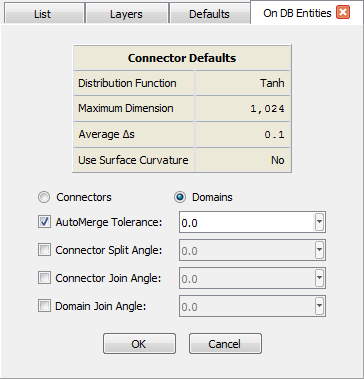
At the top of the panel, there is a Connector Defaults table listing those settings which are applied in the Defaults panel for automatic connector creation. The table updates automatically if you switch to the Defaults from the On DB Entities command to make changes. The table is dynamic and only lists those settings which have been applied in the Defaults.
Below the table, there are the two radio buttons for choosing what kind of grid entity to create: Connectors or Domains. If the latter option is selected, the command will attempt to assemble connectors into new domains. Note that this option will be enabled only if either a default Dimension or Average Δs have been defined (refer to the GUI Defaults section for more information).
Keep in mind that for the Domains option to work for the creation of structured domains, the selected underlying database surface must have four edges and a default Dimension must be set.
Use the AutoMerge Tolerance option to have newly created connectors merged automatically after being created. This option is on by default and it will use the Connector tolerance defined in File, Properties. You can override as necessary by entering a new value in the associated text field.
The Connector Split Angle command is useful for automatically splitting newly created connectors where there are angular features in the database geometry. This option is generally used in conjunction with shell database entities. Check the associated checkbox to activate this option and enter the desired split angle in the text field. Any bending angles on the connector interior greater than the split angle entered will cause new connectors to be automatically split at that location.
The Connector Join Angle command is useful for automatically joining newly created connectors where there are no features in the database geometry to represent by breaks in the topology. Check the associated checkbox to activate this option and enter the desired join angle in the text field. Any bending angles at nodes less than the join angle entered will cause new connectors to be automatically joined at that location.
The Domain Join Angle command is useful for automatically joining newly created domains where there are no features in the database geometry to represent by breaks in the topology. This option is useful when creating unstructured domains over several adjacent database surfaces and where the original surface topology is not needed in the grid. Check the associated checkbox to activate this option and enter the desired join angle in the text field. Any bending angles at common connectors less than the join angle entered will cause new domains to be automatically joined at that edge.
Note that the On Database Entities command functionality is provided on the Create toolbar by two command buttons, one for Connectors on Database Entities and one for Domains on Database Entities. However, the On DB Entities panel will not open for these toolbar commands. They will automatically apply the last used panel settings and create new grid entities immediately.