Description
The Preferences panel provides controls related to the Fidelity Pointwise environment. These controls range from viewing and selection preferences to what type of output is seen in the Messages window. Changes made to the Preferences panel are saved on your system, per user, as soon as this panel is closed.
Background
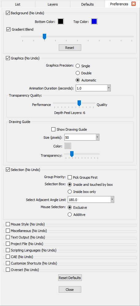
The Background frame contains all options that control how the Display window's background appears.
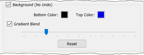
- Bottom Color: Sets the color shown in the bottom of the Display window if the Gradient Blend command is enabled.
- Top Color: Sets the color shown in the top of the Display window if the Gradient Blend command is enabled. If Gradient Blend is disabled, this color is used for the entire background.
- Gradient Blend: Sets the Fidelity Pointwise background to a blend of two colors, Bottom Color and Top Color. The slider bar allows users to specify what percentage of the screen is used by the bottom and top colors respectively.
- Reset: It is used to reset the background's Bottom Color, Top Color, and Gradient Blend to their default values.
Graphics
The Graphics frame contains the option to specify the numerical precision of the graphics calculations. By default, Fidelity Pointwise’s graphics are double precision (8 byte real numbers). It also contains tools to control the quality of transparencies and whether drawing guides should be displayed or not.
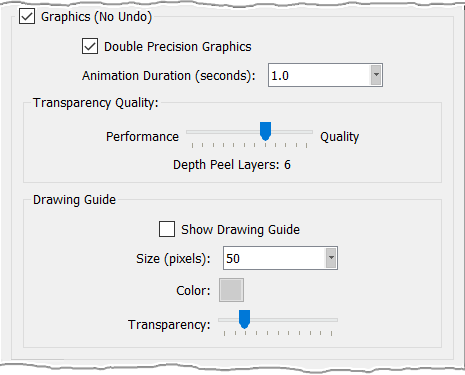
- Double Precision Graphics: Sets the graphics to use double precision (8 byte real numbers). This option has no effect on memory usage. However, with the increase in graphics fidelity, keep in mind that there will be a slight decrease in performance.
- Animation Duration (seconds): Determines how long the project database and grid are animated from the current view to a newly selected standard view or normal aligned view.
- Drawing Guide: Provides a set of tools for controlling the appearance of the drawing guide in the Display window. Show Drawing Guide toggles the display of the guide on and off. Size (pixels) determines the size of the squares forming the guide in number of pixels. Clicking the Color icon will provide a color selection dialog for customizing the guide line color. Transparency provides a level bar for setting the opacity of the guide lines.
Selection
The Selection frame provides controls for how the selection box and mouse selection behave. If you wish to always pick groups first if any, toggle on Pick Groups First.
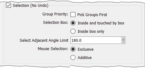
For operation of the Selection Box:
- Inside and touched by box: Sets the selection box to pick all entities that reside within or touches the box’s boundaries.
- Inside box only: Sets the selection box to pick any entity that resides entirely within the box.
For Mouse Selection:
- Exclusive: Sets the Mouse Selection for exclusive selection of an entity per mouse click. Multiple entity selection requires use of the Ctrl key.
- Additive: Sets the Mouse Selection for additive selection of entities per mouse click. Each click of individual entities adds each entity to the current selection without use of the Ctrl key. Clicking on a selected entity deselects that entity.
Mouse Style
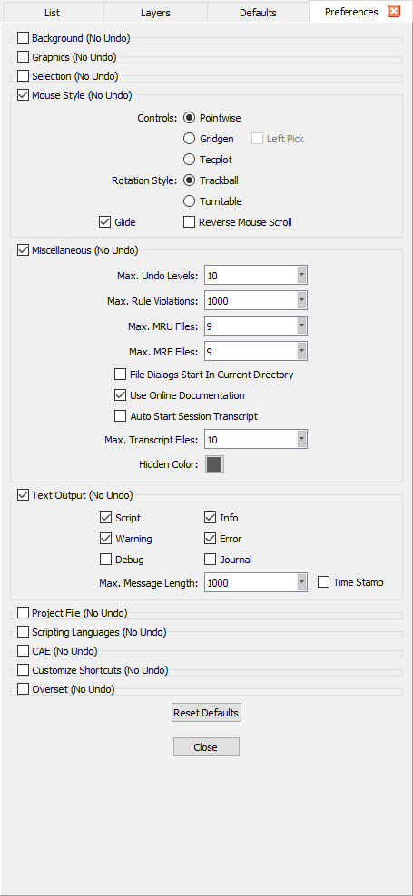
The Mouse Style frame allows you to tailor the functions of the mouse buttons to better suit your personal style or preference.
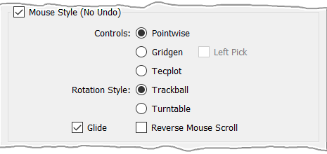
The following Controls are provided:
- Pointwise: Provides left mouse button selection. The right mouse is use for context (right-click) menus, and Shift+RMB provides model panning.
- Gridgen: Provides right mouse button selection. The left mouse is used for panning the model, and Shift+LMB provides context menus. Additionally, the Left Pick toggle will reverse the functions of the left and right mouse buttons for the Gridgen style.
- Tecplot: Provides left mouse button selection. The right mouse is used for panning the model, and Shift+RMB provides context menus.
In order to give you more flexibility when it comes to rotating your model, the following Rotation Styles are offered:
- Trackball: This is the default rotation style used by Fidelity Pointwise. It allows you to freely rotate (i.e. no axis of rotation) the view around the rotation point in 3D space.
- Turntable: This rotation style allows you to rotate the view around the rotation point. Furthermore, the rotation will be performed about the currently vertical rotation axis. Note that in this rotation style, the vertical rotation axis is allowed to tilt forward and backward (i.e. not to the sides).
Last but not least, the following options complete the Mouse Style frame:
- Glide: Determines how mouse movement controls image movement. If checked, mouse movement will give the image a velocity. That is, as long as the mouse button is pressed, the image will continue to move even when the mouse is not moving. Otherwise, the image moves only when the mouse moves.
- Reverse Mouse Scroll: Reverses the direction of zooming relative to the direction of scrolling of the middle scroll wheel.
Miscellaneous
The Miscellaneous frame contains preference settings for a diverse group of commands.
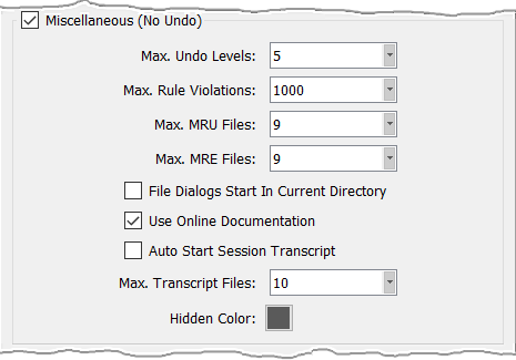
- Max. Undo Levels: Sets the number of levels that the Undo command will store. Keep in mind that all Undo levels are maintained in memory, so increasing the number of levels will increase the amount of memory necessary for Undo storage. Of course, the nature of each command and the number and type of entities it operates on will vary the memory requirement significantly from one Undo level to the next.
- Max. Rule Violations: Sets the maximum number of cells which will be displayed for all broken rules.
- Max. MRU Files: Sets the maximum number of most recently used files displayed in the File pull-down list.
- Max. MRE Files: Sets the maximum number of most recently executed scripts displayed in the Script pull-down list.
- File Dialogs Start In Current Directory: It is unchecked by default meaning the file dialogs will start at the previously visited location. To set the current working directory to the starting location of the file dialogs, toggle on this option and exit Fidelity Pointwise. The new setting will take effect the next time Fidelity Pointwise is launched. This option can also be applied as Fidelity Pointwise is started through the command line (see the Command Line Options section for more information).
- Use Online Documentation: Sets whether the online or offline version of the User Manual should be opened when the Help, User Manual command is invoked.
- Auto Start Session Transcript: Allows the creation of session transcript files to be used as a diagnostic tool. These files use the Pointwise-YYYY-mm-ddTHH_MM_SSZ.glf naming convention, where HH_MM_SSZ is in Coordinated Universal Time (UTC), and they are stored in the currently defined temporary directory. A session transcript file is created when a Fidelity Pointwise session is started and it is closed when the corresponding session ends. Note that only Max. Number of Transcript Files can be stored in the temporary directory at a time. Furthermore, when the maximum number of allowable files is reached, the oldest file will be automatically deleted and replaced with a new one.
- Hidden Color: Sets the display color of any hidden entity (see the Attributes section for more information).
Text Output
The Text Output frame controls what type of messages and how many will be output to the Messages window.
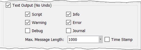
- Script messages are any standard output from a script or about its execution.
- Warning messages relate to potential problems resulting from operations performed within Fidelity Pointwise.
- Debug messages are used to debug any problems that arise in Fidelity Pointwise.
- Info messages are used to provide confirmations on the success or failure of Fidelity Pointwise commands.
- Error messages are output when a serious problem affects the performance of Fidelity Pointwise.
- Journal messages show the equivalent script commands being used interactively.
For a more detailed explanation of these message types, refer to the Messages Window section which discusses the Messages window.
- Max. Message Length: Allows you to specify the maximum length of the output messages up to 10,000 characters.
- Time Stamp: Toggles on printing of the current time with each text message written to Messages. Note some commands, such as block initialization, always provide a time stamp for reference.
Project File
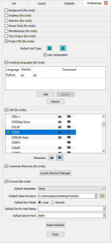
The Project File frame contains an entity type preference and the option to specify whether compression should be used or not when a project file is saved.
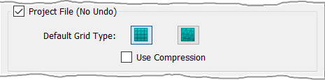
- Default Grid Type: Provides a grid type preference for whether new domains and blocks will be structured or unstructured.
- Use Compression: It is unchecked by default meaning project files will not be compressed when saved. Keep in mind that file compression will result in smaller files at the expense of a decrease in I/O performance.
Scripting Languages
Fidelity Pointwise has the capability to execute scripts written in any language. Note that only the Tcl interpreter is provided by Fidelity Pointwise; all other interpreters must be obtained separately from their respective sources.
The ability to execute Tcl-based Glyph commands is possible through a TCP server within Fidelity Pointwise that accepts Glyph commands from a client and returns the result of the command back to the client. The communication between a given script interpreter and the TCP server is facilitated by a simple communication script that needs to be implemented in the appropriate scripting language.
An example of the communication script written in Python language is available in two ways:
An example of the communication script written in Perl language is available on GitHub: Glyph Client Perl
The Scripting Languages frame controls the different scripting languages that can be executed.
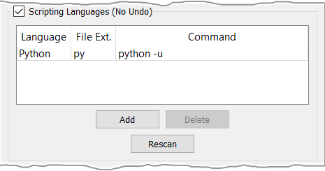
- Language: Must contain a unique descriptive name for each scripting language. The information contain in this column will be used to populate the list of accepted file types in the Run a Script File file browser that appears when a script is run using the Execute command.
- File Ext.: Must contain the file extension associated to each scripting language; the file extension does not necessarily have to be unique. The information contain in this column will be used to populate the list of accepted file types in the Run a Script File file browser that appears when a script is run using the Execute command.
- Command: Must contain the command line used to execute the script; the command does not necessarily have to be unique.
- Add: Is used to add a new entry at the bottom of the configuration table. By default, the new entry will contain the default values Language and ext in the Language and File Ext. columns respectively.
- Delete: Is used to remove the currently selected item from the configuration table. Note that this button is enabled when one element of the table is selected.
- Rescan: Is used to scan the system for installed scripting languages. This command will look for the following languages: Python, Perl, Ruby, and Lua. Any found language missing from the configuration table will be automatically added. Note that any other scripting languages can be manually added to the configuration table.
CAE
The CAE frame provides controls to define the default CAE solver for which you are building a grid (indicated by the green chevron) as well as the default dimension.
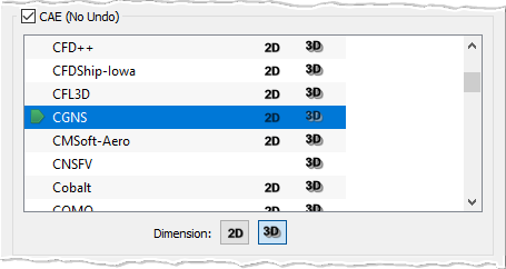
For a more detailed explanation on the available CAE solvers and dimensions, please refer to the Select Solver and Set Dimension sections respectively.
Customize Shortcuts
The Customize Shortcuts frame provides a single control to Launch Shortcut Manager. An example of the Shortcut Manager dialog is provided in the image below. Features of the dialog are described following the image.
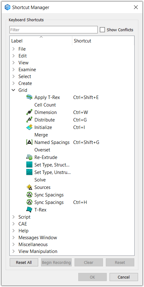
- Filter: Use the Filter text field to enter a string which will be matched to command names or shortcuts in the table, thus reducing the table list to only those matching the string.
- Show Conflicts: Toggle on the Show Conflicts checkbox to have only shortcuts with conflicts displayed in the table.
- Table: Use the table to select a command/shortcut which you would like to provide with a new shortcut or Clear or Reset the shortcut.
- Reset All: Use Reset All to have all command shortcuts returned to their default state as installed.
- Begin Recording: Select a command in the table and click Begin Recording to have a new shortcut key sequence recorded.
- End Recording: Once recording is started, Begin Recording is replaced by End Recording to complete the shortcut recording process.
- Clear: Select a command in the table and click Clear to have its corresponding shortcut deleted.
- Reset: Select a command in the table and click Reset to have the command's corresponding shortcut restored to its default state.
Overset
The Overset frame provides options to define basic overset parameters controlling where the overset data should be stored, what overset assembler should be run, and whether the overset assembler will be run locally or remotely.
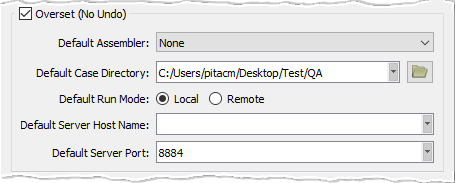
- Default Assembler: Use the pull down list to select the default overset assembler to be run. Note that if the None option is selected (default value in the list), all the overset functions in Fidelity Pointwise will be disabled.
- Default Case Directory: Use the Open Folder button to launch the file browser that will allow you to specify the location of the case directory. All the data related to the overset case at hand generated by Fidelity Pointwise and by the overset assembler will be stored in this location.
- Default Run Mode: This option allows you to specify whether the overset assembler will be run locally or remotely.
- Default Server Host Name: Use this input field to specify the name of the remote system on which the overset assembler will be run.
- Default Server Port: Use this input field to specify the port in the remote system that will be used to communicate Fidelity Pointwise with the remote overset daemon.