Description
Based on the way the intersection rays are cast, there are four possible projection types to be performed:
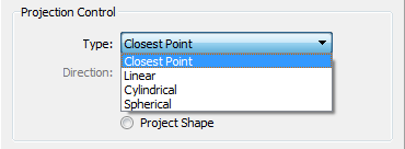
Closest Point
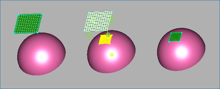
Closest Point projection is orientation independent. Points are simply moved to the closest point on the database. This procedure is also known as a normal projection because the rays cast through each point will intersect the database orthogonally. An example of a Closest Point projection of a domain onto a hemispherical surface can be seen in the figure below.

This projection method is the easiest to apply since it requires the least amount of setup. However, it should be applied with care since it sometimes is not readily apparent beforehand which is the closest database location.
Linear
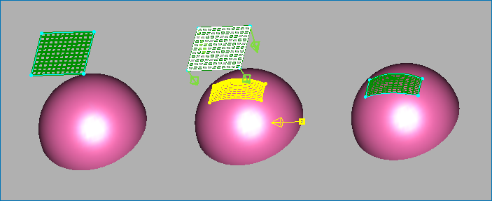
In Linear projection, points are projected along parallel rays. The ray cast direction can be along the Display window's line of sight (default), along a saved orientation, or along a selected principal axis.
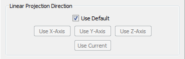
The Linear Projection Direction frame provides several options for setting the ray cast direction:
- Use Default: Sets the ray cast direction along the normals of the selected domain. This option ensures that the ray cast direction is based on the shape of the domain.
- Use X-Axis: Sets the ray cast direction along the x-axis.
- Use Y-Axis: Sets the ray cast direction along the y-axis.
- Use Z-Axis: Sets the ray cast direction along the z-axis.
- Use Current: Sets the ray cast direction so that rays are cast through the points and along the current line of sight vector. This option requires that you orient the view so that you are satisfied that the rays cast will intersect the target database in the desired manner.
Linear projections are general purpose and can be used in most cases with easily predicted results. It is recommended that you use an orthonormal viewing transformation when orienting the image prior to projection.
An example of a linear projection of a domain onto a hemispherical surface can be seen in the figure below.

Cylindrical
Cylindrical projection is named for its analogy with a cylindrical coordinate system. This method projects grid points along rays relative to one of the principal axes or a user-defined axis of projection. The rays emanate orthogonally from the axis and pass through each point.

The Cylindrical Axis frame provides several options for setting the projection axis and direction:
- XYZ: Is a point placement text field for entering the coordinates of an arbitrary axis of projection.
- Direction: Sets the direction of the axis of projection.
- Use X-Axis: Sets the x-axis as the axis of projection.
- Use Y-Axis: Sets the Y-axis as the axis of projection.
- Use Z-Axis: Sets the z-axis as the axis of projection.
Cylindrical projections are useful for projecting points onto ducted geometries such as the inside of an aircraft engine intake duct. An example of a cylindrical projection of a domain onto a hemispherical surface can be seen in the figure below.
Spherical
Spherical projection is named for its analogy with a spherical coordinate system. This method projects points along rays relative to a user-defined point. The projection rays emanate from the point and pass through each point.

The Spherical Center Point frame provides two options for setting the projection center point:
- XYZ: Sets the center point of the projection to the specified XYZ values.
- Use Origin: Sets the center point of the projection to the origin (0,0,0).
Spherical projections are useful for projecting points onto blunt geometries such as the nose of a missile. An example of a Spherical projection of a domain onto a hemispherical surface can be seen in the figure below.