Use the Automatic Surface Mesh command to access the tools that will enable you to
automatically create unstructured domains on a watertight database model based on specified
meshing resolution goals and grid quality constraints.
In the solid modeling approach, Fidelity Pointwise creates database models and quilts
while importing the initial CAD data (File, Import, Database). Models are
topological CAD entities that allow for watertight meshing over gaps and cracks existent in the
underlying geometry. Quilts, on the other hand, are meshing regions defined at the CAD
level.
The recommended starting point to use the Automatic Surface Mesh command is a
watertight database model with the meshing regions properly defined (i.e. a quilted watertight
model). Once these initial conditions are met, the command is designed to create an unstructured
surface grid constrained to the underlying database model in an automated manner. The objective
of this command is to create the desired surface grid with minimum and intuitive input in the
form of meshing goals. Furthermore, these goals fall into two main categories: mesh resolution
(i.e. target sizing) and mesh quality constraints.
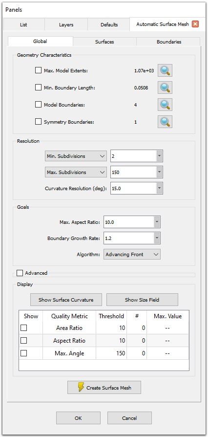
Upon invoking this command, you will be presented with the Automatic Surface Mesh
panel shown above. The panel is split into three tabs: Global, Surfaces, and
Boundaries.
- Global: This panel presents the geometric characteristics of the selected
database models. It also contains tools to define the meshing resolution goals, its quality
constraints, and some additional advanced parameters to control the characteristics of the
resulting surface mesh.
- Surfaces: This panel contains tools for adjusting the display style
within the Automatic Surface Mesh command and for specifying Resolution
and Mapping filters, which allow you to assign specific target edge lengths for
each quilt and specify which quilts receive a mapped meshing treatment (i.e. the resultant
unstructured domains are mapped to and retain the appearance of underlying structured domains).
- Boundaries: This panel contains tools for controlling which edges receive
anisotropic clustering using 2D T-Rex boundary conditions and how these boundary conditions
are defined.
Note: All the settings in the Automatic Surface Mesh
functionality are stored in the Fidelity Pointwise project file as part of the Fidelity Pointwise environment.
Additionally, these settings can also be stored in a separate environment file using the Save Environment As command
available in the File menu. This capability enables you to reuse the same
Automatic Surface Mesh settings with different geometries without the need to
re-define them.
For more on Automatic Surface Mesh, choose a topic below: