Description
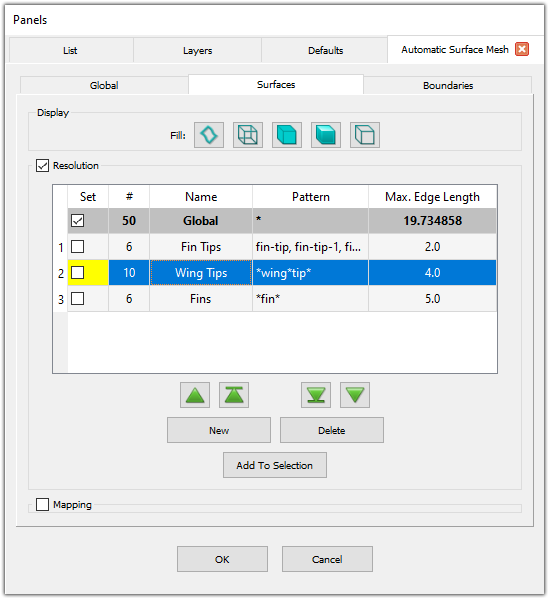
The Surfaces panel provides tools for adjusting the display style within the Automatic Surface Mesh command, for assigning specific target edge lengths on a per-quilt basis, and for specifying which quilts should receive the special mapped treatment.
Display
The Display frame provides tools for adjusting the display style of individual quilts within the Automatic Surface Mesh command. Select a quilt and change its display style to one of five options: Boundaries (Resolution
The Resolution frame provides tools for creating, assigning, and deleting resolution filters which allow you to specify target edge lengths on a per-quilt basis.Note: The Resolution and Mapping frames are mutually exclusive (i.e. only one frame can be open at a time). This removes confusion as to which filter type you are currently editing, since both filter types allow you to set entities explicitly using the Display window.
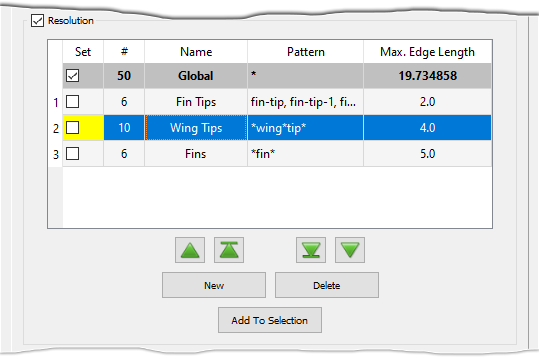
The first row in the Resolution table shows the Global resolution filter, which contains all quilts by default. The columns of this filter are populated by the settings on the Global tab and cannot be edited nor can this filter be deleted.
The buttons (New, Delete, Add to Selection,
![]() ,
,
![]() ,
,
![]() , and
, and
![]() ) and
first 4 columns in the table (priority, Set, #, and Name)
all function the same as other filters in the Flashpoint toolset. Please refer to the
Flashpoint Filters section for more information.
) and
first 4 columns in the table (priority, Set, #, and Name)
all function the same as other filters in the Flashpoint toolset. Please refer to the
Flashpoint Filters section for more information.
Note: Resolution filters are the only filter type within the Flashpoint toolset that does not currently make use of filter pattern tables. Instead, you can specify multiple patterns in the Pattern field using a comma separated list. To edit the pattern for resolution filters, simply double click in the Pattern column of the Resolution table.
Edit the Pattern column to define a filter pattern containing one or more comma-delimited wildcard patterns. If a filter's pattern list is empty, the filter is disabled. Refer to the Wildcard Pattern Matching section of the Flashpoint Filters page for more information on specifying wildcard patterns.
Edit the Max. Edge Length column to set the desired maximum edge length for the resolution filter. Leaving the Max. Edge Length column empty turns the filter off.
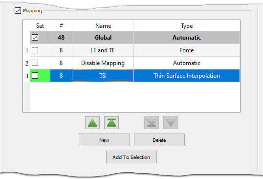
Mapping
The Mapping frame provides tools for creating, assigning, and deleting mapping filters which allow you to specify which quilts receive special mapped meshing treatment.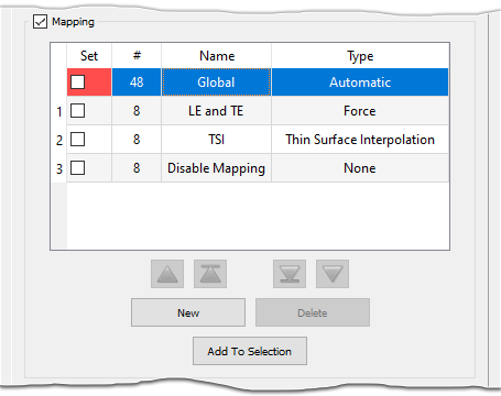
The Mapping table is similar in structure to the Resolution table discussed above. As before, the first row in the Mapping table shows the Global mapping filter, which contains all quilts by default. The columns of this filter cannot be edited nor can this filter be deleted.
The buttons (New, Delete, Add to Selection,
![]() ,
,
![]() ,
,
![]() , and
, and
![]() ) and
first 4 columns in the table (priority, Set, #, and Name)
all function the same as other filters in the Flashpoint toolset. Please refer to the
Flashpoint Filters section for more information.
) and
first 4 columns in the table (priority, Set, #, and Name)
all function the same as other filters in the Flashpoint toolset. Please refer to the
Flashpoint Filters section for more information.
User-Defined Mapping Filters
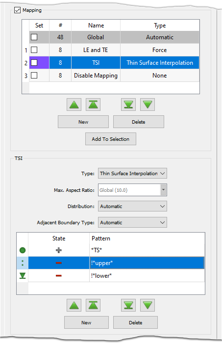
Selecting a user-defined filter in the Mapping table brings up a secondary frame with the same name as the selected filter that contains controls for editing the filter definition.
Use the Type pull down list to select the desired mapping filter type from four options:
- Automatic: Determines the suitability of the assigned quilts for mapped
meshing based on the default qualification parameters. This is this type for the
Global mapping filter, which contains all quilts by default.
Note: Not all quilts are eligible for mapped meshing treatment, which is intended for quilts that represent thin surfaces with 4 boundaries. If you expect a quilt to receive mapped meshing treatment and it does not, you can hover over the domain while in the Automatic Surface Mesh panel to display more information in the probe area of the status bar. For more information about probe messages for mapped meshing treatment, refer to the section on the Mapped Subdivision Ratio parameter in the Advanced frame of the Global tab.
- None: Specifies that no mapped meshing treatment be applied to the assigned quilts.
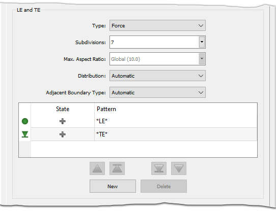
- Force: Explicitly applies mapped meshing treatment to the assigned
quilts, provided that they meet certain criteria. After meshing, the resultant unstructured
domains are linked to underlying structured domains to retain their structured
appearance. In the situation when mapped meshing fails for a quilt, Thin Surface
Interpolation is used instead.
Tip: It is a good idea to go ahead and assign quilts that you want to receive mapped meshing treatment (such as blunt trailing edges) to a mapping filter with the Force type. This produces more consistent results if your settings (and name patterns) are being used across multiple similar geometries and avoids having to re-run the Automatic Surface Mesh command if the Automatic type fails to identify the quilt as a candidate for mapped meshing treatment.
When Type is set to Force, the Subdivisions parameter appears and can be used to specify the desired number of subdivisions along the short sides of the mapped quilts.
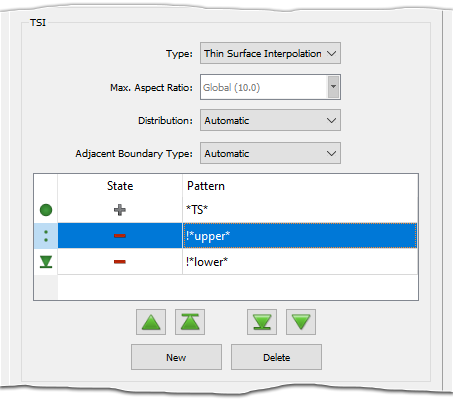
- Thin Surface Interpolation: Applies the Thin Surface Interpolation algorithm to the resultant unstructured domains to give a structured-like appearance without strictly requiring the domain be computationally balanced. For more information on the Thin Surface Interpolation algorithm, see the Algorithm section of this User Manual.
Use the Max. Aspect Ratio parameter to specify the target maximum aspect ratio for the quilts assigned to the filter. By default, the Max. Aspect Ratio is set to the value specified on the Global tab (displayed in gray text for convenience).
Note: During the Automatic Surface Mesh process, the mapping filter Max. Aspect Ratio is applied after the stretching filter Max. Aspect Ratio. To avoid confusion, it is recommended to use consistent values for both types of filters.
Use the Distribution parameter to control the distribution of points along the short sides of the mapped domains. Distribution has two options:
- Automatic: Automatically syncs the clustering of points across both short sides of the mapped surface and also with the clustering on adjacent surfaces. Automatic is the default setting and is the preferred option for thin surfaces that maintain a constant width across their length.
- Equal: Applies an equally spaced distribution of points to each short side of the mapped surface. This option is ideal for thin surfaces that have varying height along their length (such as tapered trailing edges on wings).
Tip: It is a good idea to use the Adjacent Grid option for Adjacent Boundary Type whenever you use the Equal option for Distribution because this will ensure a smooth transition in cell size from the mapped domain to the adjacent domains.
Use the Adjacent Boundary Type parameter to control how anisotropic cells are influenced by the mapped surface. Adjacent Boundary Type has two options:
- Automatic: Applies anisotropic clustering on the adjacent surfaces according to the stretching filter settings for the long edges of the mapped surface. Automatic is the default option.
- Adjacent Grid: Applies anisotropic clustering on the adjacent surfaces using a 2D T-Rex Adjacent Grid boundary condition. This option should be chosen whenever the Distribution is set to Equal, since it allows for varying anisotropic cell height along the length of the long edges.
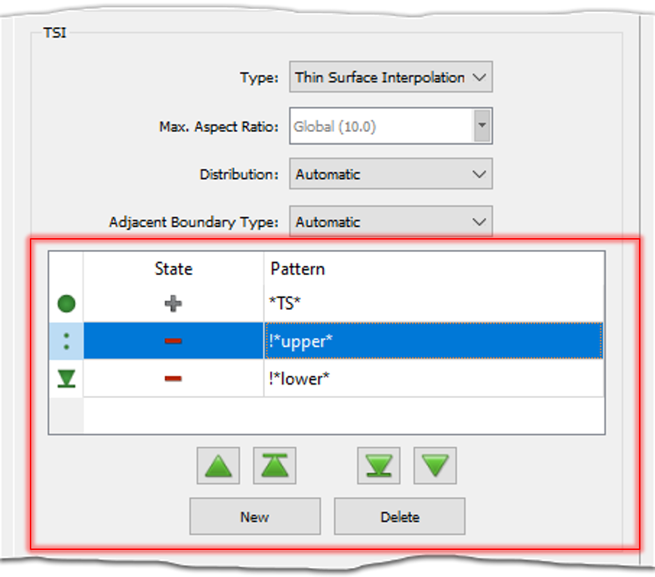
The table at the bottom of the mapping filter's frame displays the set of patterns that determine which quilts are selected by the filter. This filter pattern table functions similarly to other filter pattern tables within the Flashpoint toolset. Please refer to the Filter Pattern Tables and Wildcard Pattern Matching sections on the Flashpoint Filters page for more information on defining filter patterns.
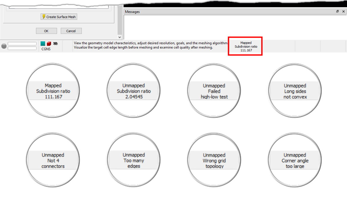
Understanding Why A Surface Doesn't Get Mapped
After the Create Surface Mesh command is finished, hovering the mouse over the domains displays information about whether or not the domain is mapped in the probe area of the Status Bar. Domains that are mapped also display the computed subdivision ratio while domains that are unmapped show information about why it was classified as such. Please click the Mapped Domain Probe Messages button below to view a table showing the possible probe messages that could be displayed as well as their meanings.
| Message | Meaning |
|---|---|
| Too many edges. | The definition of the unstructured domain has more than 1 edge. |
| Not 4 connectors. | The domain is not defined by at least 4 connectors. |
| Wrong grid topology. | A node or connector was used an incorrect number of times in the definition of the domain. Mapped domains expect each node to be used exactly twice and each connector to be used exactly once. |
| Not 4 nodes. | The loop of connectors defining the domain does not contain at least 4 nodes. |
| Invalid grid. | At least one of the connectors is undimensioned. |
| Failed high-low test. | The connectors in a mapped domain are expected to alternate their numbers of subdivisions: high-low-high-low. |
| Long sides not convex. | At least one high subdivision connector is not classified as convex. |
| Subdivision ratio | The ratio between the low subdivision count and the high subdivision count did not meet the specified limit. |
| Side ratio | The ratio between a short side connector's current dimension and the target dimension (for a balanced structured domain) is too great. |
| Subdivision: Length ratio | The length ratio is too high. The length ratio is computed as a ratio of two ratios: the subdivision ratio and the ratio between the average lengths of the short and long sides. |
| Span varies too much. | The linear distance between sampled points along the high subdivision connectors varies too much from the length of the short side connectors. |
| Quilt has zero area. | The computed quilt area is below the tolerance. |
| Failed area ratio test. | The ratio between the expected area and the computed quilt area is too great. The expected area is calculated by subdividing the long sides into segments, connecting the ends of corresponding segments, and summing the quadrilateral areas. |
| Corner angle too large. | A quad in one of the corners would have an included angle exceeding the specified target limit. This message is only possible when the Algorithm is set to Quad Dominant. |
| Invalid mapping. | The structured domain was unbalanced. |
| No obvious corners. | Four concave corners could not be identified. |
| No isolated short side. | The short side could not be identified. This usually means that two or more adjacent sides all had the same lowest number of subdivisions. |
| User disabled mapping. | The user specified no mapping for the quilt (i.e. the quilt is assigned to a mapping filter with Type set to None). |
| Thin surface mapping disabled. | Thin surface mapping was disabled. |
| Thin Surface Interpolation. | The quilt is assigned to a mapping filter with Type set to Thin Surface Interpolation. |
| User specified as forced. | The quilt is assigned to a mapping filter with Type set to Force. |
| Structured domain was unbalanced. | The quilt met all requirements for mapping. However, the unstructured domain could not be mapped due to the underlying structured domain being unbalanced. The domain will be mapped using the TSI type instead. |
| Convex corner detected. | The domain contains at least one convex corner. |