Description
There are a number of commands that optionally take XYZ or UV coordinates as input, such as Create, Draw Curves, Edit, Transform, or Edit, Tweak. For consistency in user expectation, a common Point Placement frame is used with essentially the same input options wherever it is used. For efficiency in the remainder of this manual, this set of options will be discussed once here. Note that in all text input fields multiple input values are delimited by a space and only spaces are accepted as a delimiter. See the Text Entry Fields section for more more details on entering text.
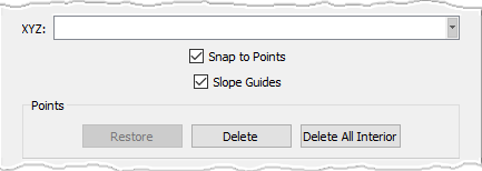
In the image above, we present the standard options to explicitly specify the Cartesian coordinates of a new point:
- XYZ: Enter the XYZ coordinates of the new point being created.
- Snap to Points: If checked on, this option allows you to specify the location of a point by picking any selectable point
directly on the Display window. Snapping is taking place when a bullseye cursor is displayed (
 ).
).
- Slope Guides: This option allows you to ensure that the curve being created/edited is tangent/orthogonal to an existing curve or normal to a database surface. With the option checked on, and with any control point of the curve being created/edited shared with another existent curve, slope guides tangent and orthogonal to the existent curve at the shared point's location will be shown in the Display window. Moreover, if the existent curve is constrained to a database surface, an additional guide normal to the surface at the shared point's location will also be shown. To further understand how to use this feature with different types of curves, please review the 2 Point Curves and Draw Curves sections.
During curve creation or edit, a Points frame with Restore, Delete and Delete All Interior options is available. Delete removes the last point placed or selected point from the definition of the curve. When editing existing points, Restore will return a point to its original location prior to the last edit performed. Only the last edit is remembered for Restore. Delete All Interior will automatically remove all interior control points. See the Deleting Control Points section for more details on removing control points.
Note: In all text input fields multiple input values are delimited by a space; only spaces are accepted as a delimiter.
Additional, less frequently used options, are found in the Advanced frame.

- XYZ Offset: Enter the X,Y,Z offset values to place a new point relative to the last point placed. Note that at least one point has to have already been placed for this option to be available.
- UV: Enter the two parametric coordinate values for a new or edited database constrained point. Note that for this option to be available the previous point place must be database constrained or a database constrained point must have been selected for edit using Ctrl+LMB.
- UV Offset: Enter the U,V offset values to place a new point relative to the last point placed. Note that for this option to be available the previous point place must be database constrained or a database constrained point must have been selected for edit using Ctrl+LMB.
- Normal Offset: Enter an offset value to be used to place a new point normal or perpendicular to a database curve or surface. Note that for this option to be available, the previous point place must be database constrained, or a database constrained point that has been selected for edit using Ctrl+LMB. For the Tweak command, however, this option will be always available regardless of whether the selected point is database constrained or not.
- Guide Scalar: This entry field is used in conjunction with the Slope Guides command explained above. When creating or editing a
curve supporting the Slope Guides command (i.e.
2 Points Curve (
 ) Line (
 ), Curve
(
), Curve
( ), Line on Database (
 ), Curve on Database
(
), Curve on Database
( ), and Conic
(
), and Conic
( )), if a control point on that curve shared by other curves and enforced by a Slope
Guide is selected (Ctrl key + select the point), this entry field will become enabled. The entered value represents the strength of the slope
enforcement.
)), if a control point on that curve shared by other curves and enforced by a Slope
Guide is selected (Ctrl key + select the point), this entry field will become enabled. The entered value represents the strength of the slope
enforcement.
The Projection frame provides tools for creating projected points. To create a projected point, you must first place a temporary point or select an existing point using Ctrl+LMB. Choose either the Linear or the Closest Point projection type, and click on Project Point to place the point on an underlying database surface.
Tip: You can use the point probe shortcuts (Ctrl+Shift+MMB for all platforms and Alt+RMB for Windows platforms) within any Fidelity Pointwise command. If you need the coordinates of a point on your geometry for use in a command’s text entry field, simply use the point probe on the point, copy the point’s coordinates that are output into the Messages window, and paste into the desired text field.
Once a first point has been defined, the Movement Restrictions option is no longer grayed out. Refer to the View Manipulation, Keyboard and Mouse section for information regarding coordinate systems used by Fidelity Pointwise.
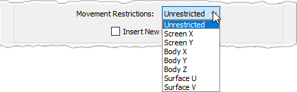
Use the pull-down list to choose from the following options:
- Unrestricted: Allows the cursor to move freely in an arbitrary drawing plane which is parallel to the plane of the screen and passes through the first point defined.
- Screen X: Forces the cursor to follow only a screen-X coordinate line which passes through the first point placed.
- Screen Y: Forces the cursor to follow only a screen-Y coordinate line which passes through the first point placed.
- Body X: Forces the cursor to follow only a body-X coordinate line which passes through the first point placed.
- Body Y: Forces the cursor to follow only a body-Y coordinate line which passes through the first point placed.
- Body Z: Forces the cursor to follow only a body-Z coordinate line which passes through the first point placed.
- Surface U: Forces the cursor to follow only a parametric U coordinate line in the database curve or surface on which the first point was placed.
- Surface V: Forces the cursor to follow only a parametric V coordinate line in the database curve or surface on which the first point was placed.
Finally, during curve creation or edit, the Insert New Points checkbox is available. This controls whether new points added will go automatically at the end of the curve definition, or if they will be inserted as a new point in the nearest bay.