In a nutshell, the Split command is used to split a selected entity. The way in which an entity can be split and the options available in the Split panel depend on the type of entity to be split. The table below presents the types of entities currently available for splitting:
Note: The Split command can process one entity at a time. This means that the command will become disabled if several entities are selected at once.
| Data Type | Entity Type |
|---|---|
| Database | Curves, ruled surfaces, surfaces of revolution, linear sweep surfaces, fillet surfaces, Coons patches, shells, quilts, and models |
| Grid | Connectors, structured domains, structured blocks, unstructured blocks, voxel blocks |
| Source | Curves |
For more information on the different entity types available in Fidelity Pointwise, please review the Terminology and Data Hierarchy pages.
Tip: Note that when entities belonging to a group are split, the resulting entities will remain in the original group.
A connector, a database curve, or a source curve can be split in one of the following ways:
When one of these types of entity is selected for splitting, the presented Split panel will look as shown in the image below. Two frames group the controls that will allow you to define how to split the selected entities: Split Location and Curve Options.
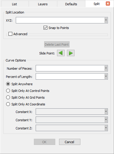
The Split Location frame present options to explicitly define the location(s) at which the selected entity should be split.
Tip: The split location can be explicitely defined using the options in the Split Location frame or it can be specified by selecting a point directly in the Display window.
In between the Split Location and Curve Options frames, you will find two additional options to manipulate a defined split point:
The Curve Options frame presents options to define the split location(s) based on the characteristics of curve being split.
Additional capability for splitting connectors, database curves, and source curves into a specific number of equal-length split pieces is provided by the
Split Into Pieces command located in the Edit toolbar: ![]() . You can simply
select at least one connector or curve and enter a number into the text field on the toolbar to split the entity into that number of equal-length pieces. Keep
in mind that this toolbar feature allows you to split multiple connectors and curves at once each into the same number of equal pieces. You may need to use
the Customize command to add this control to your Edit toolbar.
. You can simply
select at least one connector or curve and enter a number into the text field on the toolbar to split the entity into that number of equal-length pieces. Keep
in mind that this toolbar feature allows you to split multiple connectors and curves at once each into the same number of equal pieces. You may need to use
the Customize command to add this control to your Edit toolbar.
The following types of database surfaces can be split using this feature: ruled surfaces, surfaces of revolution, linear sweep surfaces, fillet surfaces, and Coons patches. Furthermore, these types of surfaces can be split at a certain location in a given parametric direction (i.e. U, V) and also along a discontinuity.
When one of these types of entities is selected for splitting, the Split panel will look as shown in the image below. Two frames group the control that will allow you to define the location and direction of the split: Split Location and Split Direction.
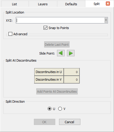
Note that the options contained in the Split Direction frame as well as the Delete Last Point and Slide Point options have been described in the Splitting by Curve section above. The options presented in the Split At Discontinuities frame places points along the surface where discontinuities are found. Last but not least, the option in the Split Direction frame are used to define the parametric direction of the split:
Database quilts formed by two or more underlying trimmed surfaces and database models containing two or more quilts can be split into their constituent parts using this command. Alternatively, you can use this command to split off a set of constituent trimmed surfaces from a quilt or a set of constituent quilts from a model. When either a database quilt or a model is selected for split, the Split panel will look as shown in the image below.
Note: Selecting a database quilt formed by a single underlying trimmed surface or a database model containing a single database quilt will not enable the Split command. This is due to the fact that such entities cannot be split into their constituent parts as each has a single constituent part.
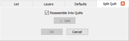
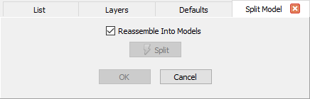
The only difference between these two panels is the checkbox options that will change depending on whether you are splitting a database quilt or a database model. When a database quilt is selected, the Reassemble Into Quilts will allow you to reassemble the quilts remaining after the split operation into as few quilts as possible. Likewise, when a database model is selected, the Reassemble Into Models option will allow you to reassemble the models remaining after the split operation into as few models as possible.
Upon invoking the Split command, note that the boundaries of all the constituent parts of the selected database quilt or model are automatically rendered in green color and are made selectable. This will aid in the quick selection of the parts that need to be split off from the database quilt or model. The Split button will perform the split operation according to the current selection.
For example, if you would like to split a larger database quilt formed by multiple underlying trimmed surfaces into its constituent parts, you must select the quilt to be split and access the command. As indicated, the boundaries of all the individual trimmed surfaces forming the larger quilt are rendered in green and are made selectable. Simply select all the trimmed surfaces, make sure the Reassemble Into Quilts option is unchecked, and click Split. Note that the larger quilt is split into its individual constituent parts.
To split off a set of database quilts from a larger quilt, you must select the larger quilt and access the command. Make sure the Reassemble Into Quilts option is checked on, select the database quilts to be split off and click Split. Note that the selected constituent parts have been split off from the larger database quilt and they have be reassembled into as few quilts as possible.
The processes to split a larger database model into its constituent parts or to split off a set of database quilts from a larger model are identical to what was explained above for quilt split operations.
A database shell can be split along the intersection between the shell itself and a user-defined plane. When a database entity of this type is selected for splitting, the Split panel will look as shown in the image below.
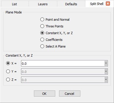
Within the Split Shell panel, several options are provided to define the plane for splitting the selected shell. Please refer to the Planes section for the discussion on the different Plane Modes: Point and Normal, Three Points, Constant X, Y, or Z, and Coefficients. The Select A Plane mode allows for a database plane to be selected directly in the Display window or the List panel.
A structured domain or block can be split at a certain location in a given computational direction (i.e. I, J, K). When one of these types of entities is selected for splitting, the presented Split panel will look as shown in the image below. Two frames group the controls that will allow you to define the location and direction of the split: Split Location and Split Direction.
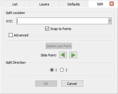

Note that the options contained in the Split Direction frame as well as the Delete Last Point and Slide Point options have been described in the Splitting by Curve section above. The options presented in the Split Direction frame change depending on whether a structured domain (IJ) or structured block (IJK) has been selected for splitting. These options are used to define the computational direction of the split:
A purely isotropic (i.e. without T-Rex cells) unstructured or voxel block can be split by specifying a physical distance from a group of selected target domains. Moreover, when the block to be split contains anisotropic cells as well (i.e. with T-Rex cells), an additional option allows to define the split location by specifying a given number of T-Rex layers off the selected target front composed of domains assigned to T-Rex boundary conditions of type Wall.
Note: The minimum allowable Distance is computed in one of two ways: If the block being split has constituent domains assigned to T-Rex boundary conditions of type Wall, this value is defined as the maximum initial spacing (Δ) associated to those boundary conditions. On the other hand, if no constituent domains are assigned to at least one Wall T-Rex boundary condition, the value is defined as the average Edge Length of those domains.
When an unstructured or voxel block is selected for splitting, the Split panel will look as shown in the image below. Two frames group he controls that will allow you to define how the split location should be determined: Split Type and either Select Target Domains (when the Distance option is selected) or Select Target Fronts (when the T-Rex Layer option is selected).
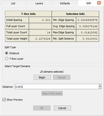
Within the Split panel for unstructured and voxel blocks (shown above), you will find specialized tools for defining the split location by specifying either a physical Distance from the selected target domains, or a specific T-Rex Layer Number off the target front. The latter option will be unavailable for purely isotropic blocks.
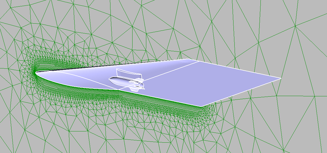
The Split Type option selected by default is Distance (see left image above). This option will work for unstructured and voxel blocks with and without T-Rex layers. Furthermore, when splitting a block with T-Rex layers, it is recommended to use the Distance option with a value slightly outside the T-Rex maximum layer height to avoid cutting oddly through the T-Rex layers and the transitioning cells adjacent to them. To use this approach, you must select the domains assigned to T-Rex boundary conditions of type Wall as your target domains. This selection is accomplished by using the options in the Select Target Domains frame. Simply click Begin and note that, by default, the original wall T-Rex fronts will populate the list that appears. You can also select the target domains directly from the Display window or the List panel. Click End to finalize the target domain selection.
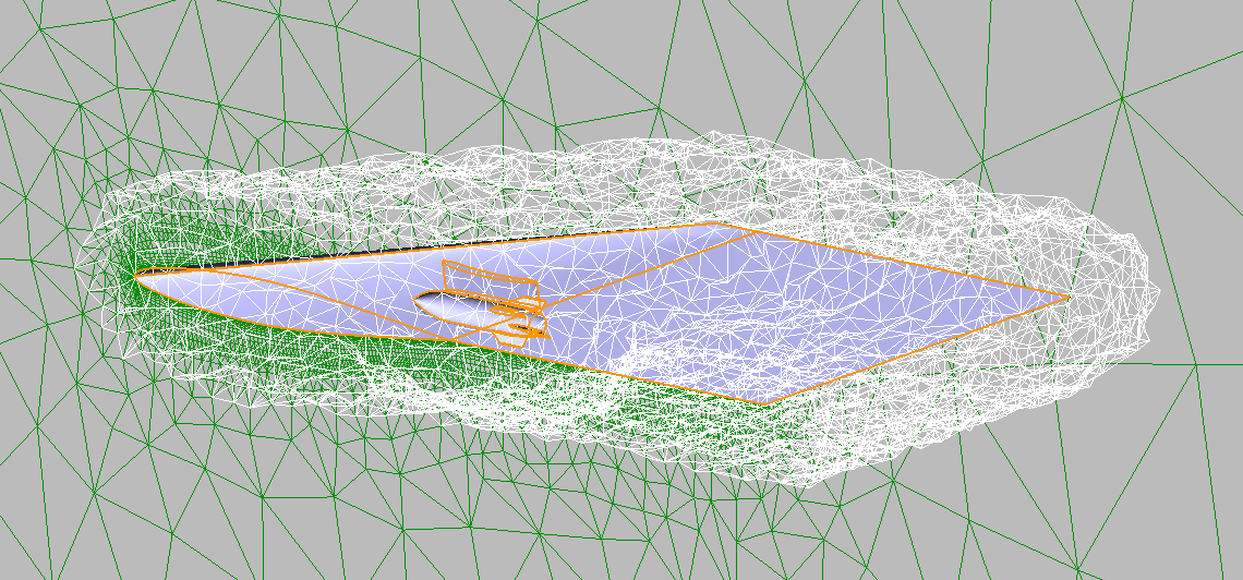
Once the target domains have been defined, the table at the top of the Split panel will get populated with useful statics on the number of T-Rex layers in the block as well as the total viscous layer height among other useful information (see image above). Using the listed Total Layer Height as a reference, enter a slightly larger value into the Distance text field. Once the distance value is entered, a preview of the split location is rendered in white in the Display window (see image below). Note that this preview can be turned off by unchecking Show Preview. Click OK to perform the split operation. Two blocks will remain: one containing primarily the T-Rex layers and the other one containing the primarily the isotropic field volume.
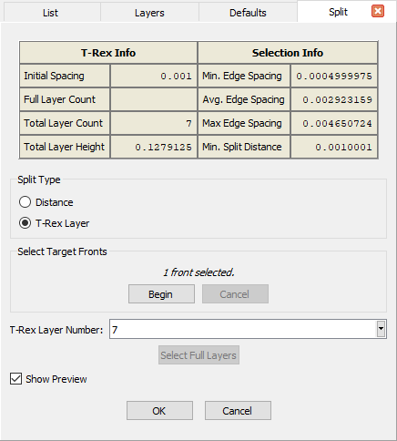
When using the Split command for T-Rex blocks via the T-Rex Layer selection for Split Type, the Split panel will change slightly (see right panel image above). Now the target fronts for the original T-Rex walls must be selected rather than any target domains. The Distance field is replaced with a T-Rex Layer Number field, and that field is automatically populated with the total layer count for the selected fronts. So basically the split location defaults to the uppermost T-Rex layer. Again, as with using the Distance option, the split location is previewed in the Display window by default as shown in the images above.